如果你也在 怎样代写电路设计Filter Design这个学科遇到相关的难题,请随时右上角联系我们的24/7代写客服。电路设计Filter Design是设计一个满足一系列要求的信号处理滤波器的过程,其中一些要求可能是相互冲突的。其目的是找到一个能充分满足每项要求的滤波器,使其发挥作用。
电路设计Filter Design过程可以被描述为一个优化问题,其中每个要求都有助于一个应该被最小化的误差函数。设计过程的某些部分可以自动化,但通常需要有经验的电气工程师来获得一个好的结果。是一个具有欺骗性的复杂课题。尽管电路设计很容易理解和计算,但其设计和实现的实际挑战是巨大的,是高级研究的主题。
my-assignmentexpert™ 电路设计Filter Design作业代写,免费提交作业要求, 满意后付款,成绩80\%以下全额退款,安全省心无顾虑。专业硕 博写手团队,所有订单可靠准时,保证 100% 原创。my-assignmentexpert™, 最高质量的电路设计Filter Design作业代写,服务覆盖北美、欧洲、澳洲等 国家。 在代写价格方面,考虑到同学们的经济条件,在保障代写质量的前提下,我们为客户提供最合理的价格。 由于统计Statistics作业种类很多,同时其中的大部分作业在字数上都没有具体要求,因此电路设计Filter Design作业代写的价格不固定。通常在经济学专家查看完作业要求之后会给出报价。作业难度和截止日期对价格也有很大的影响。
想知道您作业确定的价格吗? 免费下单以相关学科的专家能了解具体的要求之后在1-3个小时就提出价格。专家的 报价比上列的价格能便宜好几倍。
my-assignmentexpert™ 为您的留学生涯保驾护航 在EE作业代写方面已经树立了自己的口碑, 保证靠谱, 高质且原创的电路设计Filter Design代写服务。我们的专家在EE代写方面经验极为丰富,各种电路设计Filter Design相关的作业也就用不着 说。
我们提供的电路设计Filter Design及其相关学科的代写,服务范围广, 其中包括但不限于:
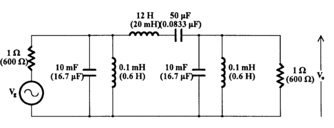
EE代写|电路设计作业代写Filter Design代考|Transformation of Elements LC Filters
Clearly, the sixth-order bandpass will be obtained from the third-order lowpass Butterworth filter by applying the lowpass-to-bandpass transformation
$$
s_{n} \rightarrow \frac{\omega_{o}}{B}\left(\frac{s}{\omega_{o}}+\frac{\omega_{o}}{s}\right)
$$
where $\omega_{o}=1 \mathrm{krad} / \mathrm{s}$ and $\mathrm{B}=100 \mathrm{rad} / \mathrm{s}$.
From the tabulated Butterworth filters, Table A.1, we find
$$
F\left(s_{n}\right)=\frac{1}{s_{n}^{3}+2 s_{n}^{2}+2 s_{n}+1}
$$
At this point, we may proceed in one of the following two alternative ways:
- We may apply the lowpass-to-bandpass transformation to obtain either the normalized or the denormalized bandpass function and proceed to realize it, i.e., to determine the circuit.
- Alternatively, we may realize the lowpass filter and apply the lowpass-to-denormalized bandpass transformation to the elements of the lowpass making use of the Table $2.5$.
EE代写|电路设计作业代写Filter Design代考|TRANSFORMATION OF ELEMENTS Active RC Filters
The procedure described above can be applied to obtain the denormalized lowpass or highpass RC active filter once the normalized lowpass function has been selected.
It is not possible to obtain the normalized or denormalized bandpass and bandstop circuits straight from the normalized lowpass, because there is no suitable transformation for this purpose. Clearly with no inductances in these circuits, it is impossible to apply the element transformations for bandpass and bandstop of Table 2.5. In this case, first the normalized bandpass or bandstop function is obtained using the corresponding frequency transformation. Next, the normalized filter is synthesized by a suitable method, as we shall see in later chapters, and then the denormalized bandpass or bandstop filter is obtained by properly scaling the filter time constants.
It has to be emphasized here that frequency transformation must be applied only to time constants, i.e., either to the capacitances or to those resistances that determine the time constants and not to those that determine the gain of the active element.
The following two examples will clarify this, while for a more formal proof the interested reader should refer to References 6 and 16 .
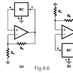
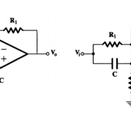
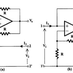
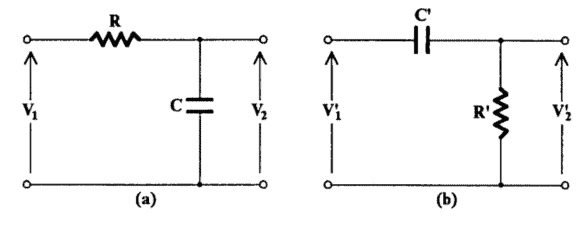
Consider first the simple RC circuit in Fig. 2.24(a). The transfer voltage ratio $V_{2} / V_{1}$ is the following:
$$
F(s)=\frac{V_{2}}{V_{1}}=\frac{1}{R C s+1}=\frac{1}{R C} \cdot \frac{1}{s+1 / R C}
$$
电路设计代写
EE代写|电路设计作业代写FILTER DESIGN代考|TRANSFORMATION OF ELEMENTS LC FILTERS
显然,通过应用低通到带通变换,将从三阶低通巴特沃斯滤波器获得六阶带通
sn→ω这乙(sω这+ω这s)
在哪里ω这=1ķr一种d/s和乙=100r一种d/s.
从列表的巴特沃斯滤波器表 A.1 中,我们发现
F(sn)=1sn3+2sn2+2sn+1
此时,我们可以通过以下两种替代方式之一进行:
- 我们可以应用低通到带通的变换来获得归一化或非归一化的带通函数并继续实现它,即确定电路。
- 或者,我们可以实现低通滤波器,并将低通到非归一化的带通变换应用到利用表的低通元素2.5.
EE代写|电路设计作业代写FILTER DESIGN代考|TRANSFORMATION OF ELEMENTS ACTIVE RC FILTERS
一旦选择了归一化低通函数,就可以应用上述过程来获得非归一化低通或高通 RC 有源滤波器。
不可能直接从归一化低通获得归一化或非归一化带通和带阻电路,因为没有适合此目的的变换。显然,在这些电路中没有电感的情况下,不可能对表 2.5 的带通和带阻应用元素变换。在这种情况下,首先使用相应的频率变换获得归一化的带通或带阻函数。接下来,通过适当的方法合成归一化滤波器,我们将在后面的章节中看到,然后通过适当缩放滤波器时间常数来获得非归一化带通或带阻滤波器。
这里必须强调的是,频率变换必须仅应用于时间常数,即应用于确定时间常数的电容或电阻,而不应用于确定有源元件增益的那些。
以下两个示例将阐明这一点,而对于更正式的证明,感兴趣的读者应参考参考文献 6 和 16。
首先考虑图 2.24 中的简单 RC 电路一种. 转移电压比在2/在1如下:
F(s)=在2在1=1RCs+1=1RC⋅1s+1/RC

EE代写 |电路设计作业代写Filter Design代考 请认准UprivateTA™. UprivateTA™为您的留学生涯保驾护航。