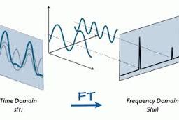
如果你也在 怎样代写信号和系统signals and systems这个学科遇到相关的难题,请随时右上角联系我们的24/7代写客服。信号和系统signals and systems信号是对一个参数如何随另一个参数变化的描述。例如,电子电路中电压随时间变化,或图像中亮度随距离变化。一个系统是任何对输入信号产生输出信号的过程。
信号和系统signals and systems是对模拟和数字信号处理的介绍,这一主题构成了许多不同领域的工程系统的一个组成部分,包括地震数据处理、通信、语音处理、图像处理、国防电子、消费电子和消费产品。
my-assignmentexpert™ 信号和系统signals and systems作业代写,免费提交作业要求, 满意后付款,成绩80\%以下全额退款,安全省心无顾虑。专业硕 博写手团队,所有订单可靠准时,保证 100% 原创。my-assignmentexpert™, 最高质量的信号和系统signals and systems作业代写,服务覆盖北美、欧洲、澳洲等 国家。 在代写价格方面,考虑到同学们的经济条件,在保障代写质量的前提下,我们为客户提供最合理的价格。 由于统计Statistics作业种类很多,同时其中的大部分作业在字数上都没有具体要求,因此信号和系统signals and systems作业代写的价格不固定。通常在经济学专家查看完作业要求之后会给出报价。作业难度和截止日期对价格也有很大的影响。
想知道您作业确定的价格吗? 免费下单以相关学科的专家能了解具体的要求之后在1-3个小时就提出价格。专家的 报价比上列的价格能便宜好几倍。
my-assignmentexpert™ 为您的留学生涯保驾护航 在信息Information作业代写方面已经树立了自己的口碑, 保证靠谱, 高质且原创的信号和系统signals and systems代写服务。我们的专家在信息Information代写方面经验极为丰富,各种信号和系统signals and systems相关的作业也就用不着 说。
我们提供的信号和系统signals and systems及其相关学科的代写,服务范围广, 其中包括但不限于:
调和函数 harmonic function
椭圆方程 elliptic equation
抛物方程 Parabolic equation
双曲方程 Hyperbolic equation
非线性方法 nonlinear method
变分法 Calculus of Variations
几何分析 geometric analysis
偏微分方程数值解 Numerical solution of partial differential equations
信号代写|信号和系统作业代写signals and systems代考|Electrical circuit
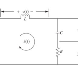
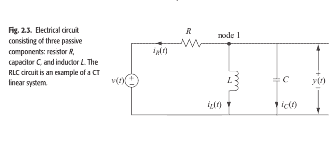
Figure $2.3$ shows a simple electrical circuit comprising of three components: a resistor $R$, an inductor $L$, and a capacitor $C$. A voltage signal $v(t)$, applied at the input of the circuit, produces an output signal $y(t)$ representing the voltage across capacitor $C$. In order to derive a relationship between the input and output signals in the RLC circuit, we make use of the Kirchhoff’s current law, which states “The sum of the currents flowing into a node equals the sum of the currents flowing out of the node.”
We apply Kirchhoff’s current law to node 1 , shown in the top branch of the RLC circuit in Fig. 2.3. The equations for the currents flowing out of node 1 along resistor $R$, inductor $L$, and capacitor $C$, are given by
resistor $R$
$$
i_{R}=\frac{y(t)-v(t)}{R}
$$
inductor $L$
$$
i_{L}=\frac{1}{L} \int_{-\infty}^{t} y(\tau) \mathrm{d} \tau
$$
capacitor $C$
$$
i_{C}=C \frac{\mathrm{d} y}{\mathrm{~d} t}
$$
Applying Kirchhoff’s current law to node 1 and summing up all the currents yields
$$
\frac{y(t)-v(t)}{R}+\frac{1}{L} \int_{-\infty}^{t} y(\tau) \mathrm{d} \tau+C \frac{\mathrm{d} y}{\mathrm{~d} t}=0
$$
which reduces to a linear, constant-coefficient differential equation of the second order, given by
$$
\frac{\mathrm{d}^{2} y}{\mathrm{~d} t^{2}}+\frac{1}{R C} \frac{\mathrm{d} y}{\mathrm{~d} t}+\frac{1}{L C} y(t)=\frac{1}{R C} \frac{\mathrm{d} v}{\mathrm{~d} t}
$$
In conjunction with the initial conditions, $y(0)$ and $\dot{y}(0)$, Eq. (2.5) completely specifies the relationship between the input voltage $v(t)$ and the output voltage $y(t)$ for the RLC circuit shown in Fig. 2.3.
In this section, we define some elementary functions that will be used frequently to represent more complicated signals. Representing signals in terms of the elementary functions simplifies the analysis and design of linear systems.
The CT unit step function $u(t)$ is defined as follows:
$$
u(t)= \begin{cases}1 & t \geq 0 \ 0 & t<0\end{cases}
$$
The DT unit step function $u[k]$ is defined as follows:
$$
u[k]= \begin{cases}1 & k \geq 0 \ 0 & k<0\end{cases}
$$
The waveforms for the unit step functions $u(t)$ and $u[k]$ are shown, respectively, in Figs. 1.12(a) and (b). It is observed from Fig. $1.12$ that the CT unit step function $u(t)$ is piecewise continuous with a discontinuity at $t=0$. In other words, the rate of change in $u(t)$ is infinite at $t=0$. However, the DT function $u[k]$ has no such discontinuity.
信号代写|信号和系统作业代写signals and systems代考|Signal operations
When a piece of an intrinsic semiconductor (silicon or germanium) is doped such that half of the piece is of $n$ type while the other half is of $p$ type, a $p n$ junction is formed. Figure 2.4(a) shows a $p n$ junction with a voltage $v$ applied across its terminals. The $p n$ junction forms a basic diode, which is fundamental to the operation of all solid state devices. The symbol for a semiconductor diode is shown in Fig. 2.4(b). A diode operates under one of the two bias conditions. It is said to be forward biased when the positive polarity of the voltage source $v$ is connected to the $p$ region of the diode and the negative polarity of the voltage source $v$ is connected to the $n$ region. Under the forward bias condition, the diode allows a relatively strong current $i$ to flow across the $p n$ junction according to the following relationship:
$$
i=I_{\mathrm{s}}\left[\exp \left(v / V_{T}\right)-1\right]
$$
where $I_{\mathrm{s}}$ denotes the reverse saturation current, which for a silicon doped diode is a constant given by $I_{\mathrm{s}}=4.2 \times 10^{-15} \mathrm{~A}$, and $V_{T}$ is the voltage equivalent of the diode’s temperature. The voltage equivalent $V_{T}$ is given by
$$
V_{T}=\frac{k T}{e}
$$
信号代写|信号和系统作业代写SIGNALS AND SYSTEMS代考|Amplitude modulator
Modulation is the process used to shift the frequency content of an informationbearing signal such that the resulting modulated signal occupies a higher frequency range. Modulation is the key component in modern-day communication systems for two main reasons. One reason is that the frequency components of the human voice are limited to a range of around $4 \mathrm{kHz}$. If a human voice signal is transmitted directly by propagating electromagnetic radio waves, the communication antennas required to transmit and receive these radio signals would be impractically long. A second reason for modulation is to allow for simultaneous transmission of several voice signals within the same geographic region. If two signals within the same frequency range are transmitted together, they will interfere with each other. Modulation provides us with the means of separating the voice signals in the frequency domain by shifting each voice signal to a different frequency band. There are different techniques used to modulate a signal. Here we introduce the simplest form of modulation referred to as amplitude modulation (AM).
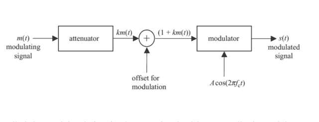
Consider an information-bearing signal $m(t)$ applied as an input to an AM system, referred to as an amplitude modulator. In communications, the input $m(t)$ to a modulator is called the modulating signal, while its output $s(t)$ is called the modulated signal. The steps involved in an amplitude modulator are illustrated in Fig. 2.5, where the modulating signal $m(t)$ is first processed by attenuating it by a factor $k$ and adding a de offset such that the resulting signal $(1+k m(t))$ is positive for all time $t$. The modulated signal is produced by multiplying the processed input signal $(1+k m(t))$ with a high-frequency carrier $c(t)=A \cos \left(2 \pi f_{\mathrm{c}} t\right)$. Multiplication by a sinusoidal wave of frequency $f_{\mathrm{c}}$ shifts the frequency content of the modulating signal $m(t)$ by an additive factor of $f_{\mathrm{c}}$. Mathematically, the amplitude modulated signal $s(t)$ is expressed as follows:
$$
s(t)=A[1+k m(t)] \cos \left(2 \pi f_{\mathrm{c}} t\right)
$$
where $A$ and $f_{\mathrm{c}}$ are, respectively, the amplitude and the fundamental frequency of the sinusoidal carrier.
It may be noted that the amplitude $A$ and frequency $f_{\mathrm{c}}$ of the carrier signal, along with the attenuation factor $k$ used in the modulator, are fixed; therefore, Eq. (2.9) provides a direct relationship between the input and the output signals of an amplitude modulator. For example, if we set the attenuation factor $k$ to $0.2$ and use the carrier signal $c(t)=\cos \left(2 \pi \times 10^{8} t\right)$, Eq. (2.9) simplifies to
$$
s(t)=[1+0.2 m(t)] \cos \left(2 \pi \times 10^{8} t\right)
$$
信号和系统代写
信号代写|信号和系统作业代写SIGNALS AND SYSTEMS代考|ELECTRICAL CIRCUIT
数字2.3显示了一个由三个组件组成的简单电路:电阻器R, 一个电感器大号, 和一个电容器C. 电压信号在(吨),施加在电路的输入端,产生一个输出信号是(吨)表示电容器两端的电压C. 为了推导 RLC 电路中输入和输出信号之间的关系,我们利用了基尔霍夫电流定律,该定律指出“流入节点的电流之和等于流出节点的电流之和。 ”
我们将基尔霍夫电流定律应用于节点 1,如图 2.3 中 RLC 电路的顶部分支所示。沿电阻器从节点 1 流出的电流方程R, 电感大号, 和电容器C,由
电阻器给出R
一世R=是(吨)−在(吨)R
电感器大号
一世大号=1大号∫−∞吨是(τ)dτ
电容器C
一世C=Cd是 d吨
将基尔霍夫电流定律应用于节点 1 并总结所有电流产量
是(吨)−在(吨)R+1大号∫−∞吨是(τ)dτ+Cd是 d吨=0
简化为二阶线性常系数微分方程,由下式给出
d2是 d吨2+1RCd是 d吨+1大号C是(吨)=1RCd在 d吨
结合初始条件,是(0)和是˙(0), 方程。2.5完全指定输入电压之间的关系在(吨)和输出电压是(吨)对于图 2.3 所示的 RLC 电路。
在本节中,我们定义了一些经常用于表示更复杂信号的基本函数。用基本函数表示信号简化了线性系统的分析和设计。
CT单位阶跃函数在(吨)定义如下:
在(吨)={1吨≥0 0吨<0
DT单位阶跃函数在[ķ]定义如下:
在[ķ]={1ķ≥0 0ķ<0
单位阶跃函数的波形在(吨)和在[ķ]分别显示在图 1 和图 3 中。1.12一种和b. 由图可见。1.12CT 单位阶跃函数在(吨)是分段连续的,在吨=0. 换句话说,变化率在(吨)是无限的吨=0. 但是,DT 函数在[ķ]没有这种不连续性。
信号代写|信号和系统作业代写SIGNALS AND SYSTEMS代考|SIGNAL OPERATIONS
当一块本征半导体s一世l一世C这n这rG和r米一种n一世在米掺杂使得该片的一半是n键入,而另一半是p类型,一个pn结形成。图 2.4一种显示一个pn结有电压在应用于其终端。这pn结形成一个基本二极管,它是所有固态器件工作的基础。半导体二极管的符号如图 2.4 所示b. 二极管在两种偏置条件之一下工作。当电压源的正极性时称为正向偏置在连接到p二极管的区域和电压源的负极性在连接到n地区。在正向偏置条件下,二极管允许相对强的电流一世流过pn结按如下关系:
一世=一世s[经验(在/在吨)−1]
在哪里一世s表示反向饱和电流,对于硅掺杂二极管,它是一个常数,由下式给出一世s=4.2×10⁻¹⁵ 一种, 和在吨是二极管温度的电压等效值。电压当量在吨是(谁)给的
在吨=ķ吨和
信号代写|信号和系统作业代写SIGNALS AND SYSTEMS代考|AMPLITUDE MODULATOR
调制是用于移动信息承载信号的频率内容的过程,以便得到的调制信号占据更高的频率范围。调制是现代通信系统中的关键组成部分,主要有两个原因。一个原因是人声的频率成分被限制在大约4ķH和. 如果通过传播电磁无线电波直接传输人声信号,则传输和接收这些无线电信号所需的通信天线将不切实际地长。调制的第二个原因是允许在同一地理区域内同时传输多个语音信号。如果同一频率范围内的两个信号一起传输,它们将相互干扰。调制为我们提供了通过将每个语音信号转移到不同的频带来分离频域中的语音信号的方法。有用于调制信号的不同技术。这里我们介绍最简单的调制形式,称为幅度调制一种米.
考虑一个信息承载信号米(吨)用作 AM 系统的输入,称为幅度调制器。在通信中,输入米(吨)调制器称为调制信号,而其输出s(吨)称为调制信号。幅度调制器涉及的步骤如图 2.5 所示,其中调制信号米(吨)首先通过将其衰减一个因子来处理ķ并添加一个 de 偏移量,使得生成的信号(1+ķ米(吨))一直都是积极的吨. 调制信号是通过将处理后的输入信号相乘产生的(1+ķ米(吨))带有高频载波C(吨)=一种因(2圆周率FC吨). 乘以频率的正弦波FC改变调制信号的频率成分米(吨)通过一个附加因子FC. 在数学上,幅度调制信号s(吨)表示如下:
s(吨)=一种[1+ķ米(吨)]因(2圆周率FC吨)
在哪里一种和FC分别是正弦载波的幅度和基频。
可以注意到,幅度一种和频率FC载波信号,以及衰减因子ķ用于调制器,是固定的;因此,方程式。2.9提供幅度调制器的输入和输出信号之间的直接关系。例如,如果我们设置衰减因子ķ到0.2并使用载波信号C(吨)=因(2圆周率×108吨), 方程。2.9简化为
$$
s(t)=[1+0.2 m(t)] \cos \left(2 \pi \times 10^{8} t\right)
$$

信号代写|信号和系统作业代写signals and systems代考 请认准UprivateTA™. UprivateTA™为您的留学生涯保驾护航。


