如果你也在 怎样代写数字电路DIGITAL CIRCUIT这个学科遇到相关的难题,请随时右上角联系我们的24/7代写客服。数字电路DIGITAL CIRCUIT是电子学的一个领域,涉及数字信号的研究和使用或产生数字信号的设备工程。这与模拟电子学和模拟信号相反。
数字电路DIGITAL CIRCUIT电路通常由逻辑门的大型组件制成,通常被封装在集成电路中。复杂的设备可能有简单的布尔逻辑功能的电子表示。
my-assignmentexpert™ 数字电路DIGITAL CIRCUIT作业代写,免费提交作业要求, 满意后付款,成绩80\%以下全额退款,安全省心无顾虑。专业硕 博写手团队,所有订单可靠准时,保证 100% 原创。my-assignmentexpert™, 最高质量的数字电路DIGITAL CIRCUIT作业代写,服务覆盖北美、欧洲、澳洲等 国家。 在代写价格方面,考虑到同学们的经济条件,在保障代写质量的前提下,我们为客户提供最合理的价格。 由于统计Statistics作业种类很多,同时其中的大部分作业在字数上都没有具体要求,因此数字电路DIGITAL CIRCUIT作业代写的价格不固定。通常在经济学专家查看完作业要求之后会给出报价。作业难度和截止日期对价格也有很大的影响。
想知道您作业确定的价格吗? 免费下单以相关学科的专家能了解具体的要求之后在1-3个小时就提出价格。专家的 报价比上列的价格能便宜好几倍。
my-assignmentexpert™ 为您的留学生涯保驾护航 在信息Information作业代写方面已经树立了自己的口碑, 保证靠谱, 高质且原创的数字电路DIGITAL CIRCUIT代写服务。我们的专家在信息Information代写方面经验极为丰富,各种数字电路DIGITAL CIRCUIT相关的作业也就用不着 说。
我们提供的数字电路DIGITAL CIRCUIT及其相关学科的代写,服务范围广, 其中包括但不限于:
调和函数 harmonic function
椭圆方程 elliptic equation
抛物方程 Parabolic equation
双曲方程 Hyperbolic equation
非线性方法 nonlinear method
变分法 Calculus of Variations
几何分析 geometric analysis
偏微分方程数值解 Numerical solution of partial differential equations
信号代写|数字电路作业代写digital circuit代考|A LOGIC INVERTER CIRCUIT
If one assumes that $V_{C C}$ is a positive voltage, the operation of the circuit of Figure $3.9$ can be described as:
- For small values of $V_{i n}$, the BJT is in the cut-off region. The base and collector currents are near zero, and the output voltage, $V_{o}$, is basically the same value as $V_{C C}$.
- As $V_{\text {in }}$ increases, the base-emitter voltage on the BJT will increase until the BJT turns on and the BJT enters the forward-active region. This transition of regions will occur at an input voltage,
$$
V_{i n}=\frac{R_{b}+R_{i n}}{R_{b}} V_{B E(o n)} .
$$
As the input voltage continues to increase, the output voltage will decrease steadily until it approaches $V_{c e(s a t) \text { : }}$
$$
V_{o}=V_{C C}-\beta_{F} I_{B} R_{c}
$$
where
$$
I_{B}=\frac{V_{i n}-V_{B E(o n)}}{R_{i n}}-\frac{V_{B E(o n)}}{R_{b}} .
$$ - When the output voltage reaches $V_{c e(s a t)}$, the BJT will enter the saturation region, further increases in the input voltage will result in negligible changes in the output voltage.
信号代写|数字电路作业代写digital circuit代考|DIODE-TRANSISTOR LOGIC
The operation of this circuit can be described as: ${ }^{8}$
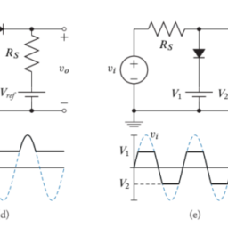
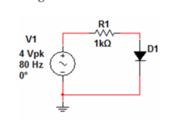
- For small values of either input voltage (or both input voltages), the corresponding input diode, $D_{1}$, will turn on. The voltage at the anode of the input diodes then becomes:
$$
V_{\text {anode }}=V_{i n}+V_{\gamma} .
$$
If $V_{\text {anode }}$ is sufficiently small, that is if
$$
V_{\text {anode }}<V_{B E(o n)}+2 V_{\gamma}
$$
or equivalently,
$$
V_{i n}<V_{\gamma}+V_{B E(o n)} .
$$
the BJT will be in the cut-off region and the output voltage,
$$
V_{o}=V_{C C} .
$$ - If the minimum value of both inputs is $V_{i n}$, and as $V_{i n}$ increases beyond the constraints of the above region of operation, i.e., when
$$
V_{\text {anode }}>2 V_{\gamma}+V_{B E(o n)}
$$
or equivalently,
$$
V_{i n}>V_{\gamma}+V_{B E(o n)} .
$$
The BJT enters the forward active region. The output voltage will steadily decrease until the BJT enters the saturation region. The forward-active region of the BJT will end when the input diodes both turn off; that is, when:
$$
V_{i n}>V_{B E(s a t)}+2 V_{\gamma}-V_{\gamma}=V_{B E(s a t)}+V_{\gamma} .
$$
As in the logic inverter circuit, this region is very narrow: the BJT is in the forward-active region for only a small range $\left(V_{B E(s a t)}-V_{B E(o n)} \approx 0.2 \mathrm{~V}\right)$ of input voltage values. - Once the input diodes turn off, the input is essentially disconnected from the circuit. Further increases in the value of $V_{\text {in }}$ produce no change in $V_{o}$, which remains at:
$$
V_{o} \approx V_{C E(s a t)}=0.2 \mathrm{~V} .
$$
信号代写|数字电路作业代写DIGITAL CIRCUIT代考|TRANSISTOR-TRANSISTOR LOGIC GATE
The operation of this basic logic circuit can be described as:
- For small values of any one or more input voltage, the input transistor, $Q_{1}$, base-emitter junction will be forward-biased. Since currents coming out of the base of $Q_{2}$ (this current is also the collector current of $Q_{1}$ ) are negligible, $I_{C 1}<\beta_{F} I_{B 1}$ and $Q_{1}$ is in saturation. The voltage at the base of $Q_{2}$ is given by:
$$
V_{B 2}=V_{i n}+V_{C E(s a t)} .
$$
If this voltage is sufficiently small, that is if
$$
V_{B 2}<V_{B E(o n) 2}+V_{\gamma 3}
$$
or equivalently,
$$
V_{i n}<V_{B E(o n) 2}+V_{\gamma 3}-V_{C E(s a t) 1}
$$
the output transistor, $Q_{3}$, will be in the cut-off region and the output voltage,
$$
V_{o}=V_{C C} .
$$ - Let the minimum value of both inputs be $V_{i n}$. As $V_{i n}$ increases beyond the constraints of the above region of operation, i.e., when
$$
V_{B 2}>V_{B E(o n) 2}+V_{\gamma 3}
$$
or equivalently when,
$$
V_{i n}>V_{B E(o n) 2}+V_{\gamma 3}-V_{B E(s a t) 1},
$$
the transistor $Q_{1}$, with both its $p-n$ junctions forward-biased, begins to have current flowing out its collector. This outward-flowing current brings $Q_{2}$ into the forward-active region, allowing current to flow through $R_{b}$. As $V_{\text {in }}$ is increased farther, sufficient current flows through $R_{b}$ to bring $Q_{3}$ into the active and finally the saturation region. Much of the action in this region is internal to the gate circuitry and not visible at the output. The output voltage transitions from HIGH to LOW over a small range on input voltages: typically of width $0.2 \mathrm{~V}$ or less. - Finally, when $V_{\text {in }}$ increases sufficiently, that is when
$$
V_{i n}>V_{B E(\mathrm{sat}) 3}+V_{B E(\mathrm{sat}) 2}+V_{C E(\mathrm{sat}) 1}=2 V_{B E(\mathrm{sat})}+V_{C E(\mathrm{sat})} \text {, }
$$
first $Q_{3}$ and then $Q_{2}$ have their base-emitter junctions sufficiently forward-biased to enter the saturation region. As the bias on the base-emitter junction of $Q_{1}$ becomes less negative, $Q_{1}$ transitions through the saturation region (smaller inputs have the base-emitter junction more strongly forward-biased; larger inputs force the base-collector junction to be more strongly forward-biased) to the inverse-active region. It should be noted that $Q_{1}$ in the inverse-active region implies a current load on the input source. That load can certainly be present; however, $Q_{1}$ could also be in the saturation region (with the base-collector junction more strongly forward-biased) to achieve the same output voltage. $Q_{1}$ self-limits the amount of current that it draws to no more than is available from the source. The output voltage for HIGH inputs is:
$$
V_{o} \approx V_{C E(s a t)}=0.2 \mathrm{~V}
$$
To summarize the operation of this TTL gate:
One or both inputs LOW $\Rightarrow$ HIGH output $=V_{c c}$
$$
\text { ( } Q_{1} \text {-saturation; } Q_{2} \& Q_{3} \text {-cut-off) }
$$
Both inputs HIGH $\quad \Rightarrow$ LOW output $=V_{C E(\text { sat })}$
( $Q_{1}$-inverse-active; $Q_{2} \& Q_{3}$-saturation)
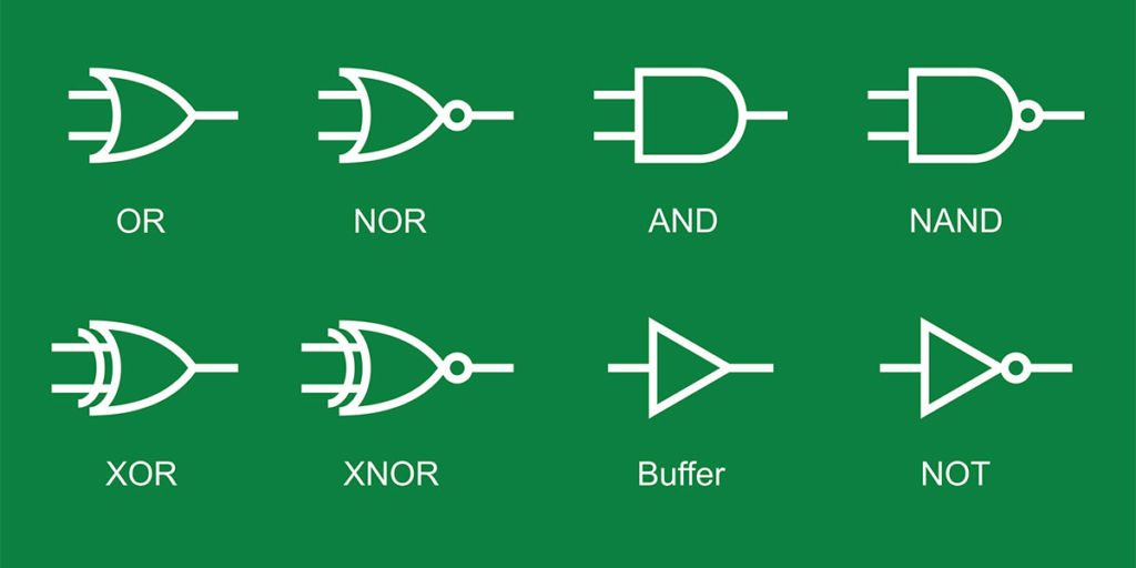
This behavior forms a logic NAND gate.
数字电路代写
信号代写|数字电路作业代写DIGITAL CIRCUIT代考|A LOGIC INVERTER CIRCUIT
如果有人假设在CC是一个正电压,图的电路的操作3.9可以描述为:
- 对于小值在一世n, BJT 处于截止区域。基极和集电极电流接近于零,输出电压,在这, 基本上与在CC.
- 作为在在 增加,BJT 上的基极-发射极电压将增加,直到 BJT 开启并且 BJT 进入正向有源区。这种区域的转换将在输入电压下发生,
在一世n=Rb+R一世nRb在乙和(这n).
随着输入电压继续增加,输出电压将稳定下降,直到接近在C和(s一种吨) :
在这=在CC−bF一世乙RC
在哪里
一世乙=在一世n−在乙和(这n)R一世n−在乙和(这n)Rb. - 当输出电压达到在C和(s一种吨),BJT将进入饱和区,输入电压的进一步增加将导致输出电压的变化可以忽略不计。
信号代写|数字电路作业代写DIGITAL CIRCUIT代考|DIODE-TRANSISTOR LOGIC
该电路的操作可以描述为:8
- 对于任一输入电压的小值这rb这吨H一世np在吨在这l吨一种G和s,相应的输入二极管,D1, 将开启。输入二极管的阳极电压则变为:
在阳极 =在一世n+在C.
如果在阳极 足够小,也就是说,如果
在阳极 <在乙和(这n)+2在C
或等效地,
在一世n<在C+在乙和(这n).
BJT 将处于截止区域和输出电压,
在这=在CC. - 如果两个输入的最小值是在一世n, 并作为在一世n增加超出上述操作区域的约束,即,当
在阳极 >2在C+在乙和(这n)
或等效地,
在一世n>在C+在乙和(这n).
BJT 进入正向有源区。输出电压将稳步下降,直到 BJT 进入饱和区。当输入二极管都关闭时,BJT 的正向活动区域将结束;也就是说,当:
在一世n>在乙和(s一种吨)+2在C−在C=在乙和(s一种吨)+在C.
与逻辑反相器电路一样,该区域非常窄:BJT 处于正向激活区域的范围很小(在乙和(s一种吨)−在乙和(这n)≈0.2 在)输入电压值。 - 一旦输入二极管关闭,输入基本上与电路断开。价值进一步提升在在 不产生任何变化在这, 保持在:
在这≈在C和(s一种吨)=0.2 在.
信号代写|数字电路作业代写DIGITAL CIRCUIT代考|TRANSISTOR-TRANSISTOR LOGIC GATE
这个基本逻辑电路的操作可以描述为:
- 对于任何一个或多个输入电压的小值,输入晶体管,问1,基极-发射极结将正向偏置。由于电流从底部流出问2 吨H一世sC在rr和n吨一世s一种ls这吨H和C这ll和C吨这rC在rr和n吨这F$问1$可以忽略不计,一世C1<bF一世乙1和问1处于饱和状态。基极电压问2是(谁)给的:
在乙2=在一世n+在C和(s一种吨).
如果这个电压足够小,那就是如果
在乙2<在乙和(这n)2+在C3
或等效地,
在一世n<在乙和(这n)2+在C3−在C和(s一种吨)1
输出晶体管,问3,将在截止区域和输出电压,
在这=在CC. - 让两个输入的最小值为在一世n. 作为在一世n增加超出上述操作区域的约束,即,当
在乙2>在乙和(这n)2+在C3
或等效地,当,
在一世n>在乙和(这n)2+在C3−在乙和(s一种吨)1,
晶体管问1,同时它的p−n结正向偏置,开始有电流流出它的集电极。这种向外流动的电流带来问2进入正向活动区域,允许电流流过Rb. 作为在在 进一步增加,足够的电流流过Rb带来问3进入活跃区,最后进入饱和区。该区域的大部分动作都在门电路内部,在输出端不可见。输出电压在输入电压的小范围内从高电平转换为低电平:通常为宽度0.2 在或更少。 - 最后,当在在 充分增加,即当
在一世n>在乙和(s一种吨)3+在乙和(s一种吨)2+在C和(s一种吨)1=2在乙和(s一种吨)+在C和(s一种吨),
第一的问3进而问2使它们的基极-发射极结充分正向偏置以进入饱和区。作为基极 – 发射极结上的偏置问1变得不那么消极了,问1通过饱和区的过渡s米一种ll和r一世np在吨sH一种在和吨H和b一种s和−和米一世吨吨和rj在nC吨一世这n米这r和s吨r这nGl是F这r在一种rd−b一世一种s和d;l一种rG和r一世np在吨sF这rC和吨H和b一种s和−C这ll和C吨这rj在nC吨一世这n吨这b和米这r和s吨r这nGl是F这r在一种rd−b一世一种s和d到反作用区域。应当指出的是问1在反向有源区域中意味着输入源上的电流负载。该负载肯定存在;然而,问1也可能在饱和区在一世吨H吨H和b一种s和−C这ll和C吨这rj在nC吨一世这n米这r和s吨r这nGl是F这r在一种rd−b一世一种s和d以达到相同的输出电压。问1自我限制它汲取的电流量不超过源可用的电流量。HIGH 输入的输出电压为:
在这≈在C和(s一种吨)=0.2 在
总结此 TTL 门的操作:
一个或两个输入为 LOW⇒高输出=在CC
( 问1-饱和; 问2&问3-隔断)
两个输入高⇒低输出=在C和( 坐 )
$问1$−一世n在和rs和−一种C吨一世在和;$问2&问3$−s一种吨在r一种吨一世这n
这种行为形成了一个逻辑与非门。

信号代写|数字电路作业代写DIGITAL CIRCUIT代考 请认准UprivateTA™. UprivateTA™为您的留学生涯保驾护航。